Implementation of Mr. Keshe's recommendations for MaGrav unit technology
This article is part of the KF Plasma Times August 2019
Published on: August 2019
Preface
For several months now, Mr. Keshe has been broadcasting important information in his Thursday morning classes that has led me to reflect in depth on what could be done to improve the performance of the basic MaGravs offered during the initiation workshops in France.
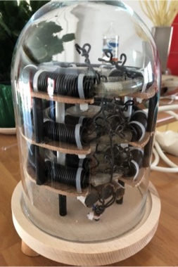
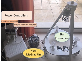
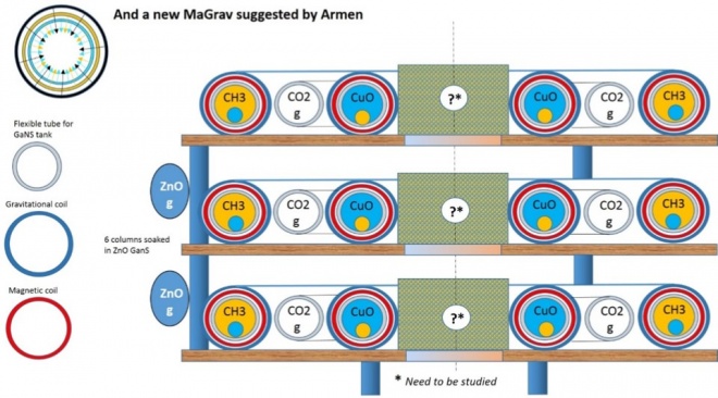
After studying the courses at length, including the basic courses to which Mr. Keshe often refers, I decided to apply all the advice proposed to create a new MaGrav, the first evolution of the basic MaGrav (Fig. 1).
Of course, it is not a question of erasing everything that has been done so far, but of developing technology. The desire to change everything is not topical and my professional past as a scientist reminds me of a golden rule: we only change one parameter at a time…
Goals
Several objectives are pursued by this work:
(a) To better understand how MaGrav works, given that Mr. Keshe has provided a lot of information to use,
(b) As owner of two basic MaGravs and a star formation with 4 spherical reactors, it is necessary to make configuration comparisons and measure - as far as possible - certain parameters,
(c) Advance towards disc technology and anti-gravity; the new MaGrav proposed in this article is part of a machine that will use this disc technology and should significantly reduce the gravitational part.
Duration of the experiment
As with the agricultural experiment, tests on this new MaGrav are ongoing. The first results are presented in this article. The experiment is being carried out without any downtime because additional tests (requiring extensive installation) to evaluate the performance of the new MaGrav will be carried out shortly and their results proposed by the end of September at the latest.
Process
I have implemented Mr. Keshe's advice as per [1-4]:
- The "visible" coils are gravitational, and the magnetic coils are housed in the gravitational coils.
- The MaGrav circuit enter input is in gravitational and the output is in magnetic.
- “The Nano coating of the coils must be done very carefully: our coils are therefore Nano coated with the soda process, then aged for several months (according to the recommendations of the basic courses).
- There is no soaking of the coils in the GaNS: the GaNS are in "tanks" pipes housed in or between the coils.
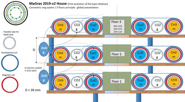
- The central sun sphere of each stage is replaced by a cylindrical tank, because Mr. Keshe mentioned several times (rightly) that spherical geometry is only important on rotating machines in order to maintain the GaNS at the equatorial plane. In our unit, the cylindrical box performs this function. Note that the GaNS mixture (50% CO2, 25% CH3 and 25% CuO) is renewed: one cannot change everything at once, otherwise you will no longer have usable results. On the other hand, this cylindrical box allows the distance between the different floors to be precisely adjusted. In the next evolutions the box will disappear.
- The connection with Soul does not fundamentally exist in the basic MaGrav. The new MaGrav incorporates 9 Nano copper tubes coated and impregnated with ZnO GaNS to have a connection of the Soul with the unit.
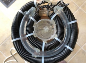
- The support plates of each floor are made of wood, very open-worked as is the support of the star formation, to facilitate and improve the dynamics of the field flows. Several designs have been studied and tested in resistance to produce a part that also allows, if assembled with application, to obtain coil windings close to the circular shape (Fig. 2), thus limiting flow and inductance disturbances.
- The inductance is more uniform because the internal wire that connected the coils to each other is removed.
- All the GaNS used are pure and desalinated. Their gestation lasted nearly 6 months, applying Sandor's advice - many thanks to him.
Figure 3 shows the layout of this first evolution of the basic MaGrav.
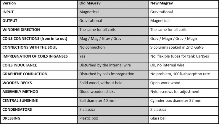
Table 1 below summarizes the comparative characteristics of the two MaGravs.
Folding of the "expected" events
After having carried out the two start-up steps (3 days of waiting and 21 days connected non-stop to the mains and refrigerator) I have connected my MaGrav to the star formation to supply the 4 brushless motors.
I have connected precision controllers to the MaGrav's input and output (Fig. 4).
The sensitivity of the control devices and the low power consumed by the 4 motors make it possible to distinguish a possible difference in consumption between the input and output of the new MaGrav.
This gap, totally unusable in quantum physics, nevertheless makes it possible to detect an operating mode, a state of the MaGrav unit.
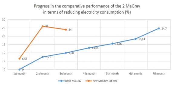
From the first month of operation, the new MaGrav has reduced power consumption.
After two months of use, this unit has reduced our consumption by a level reached by the old version after seven months of connection (Fig.5).
Values in Fig. 5 are based on the actual monthly consumption over the past six years. We had an evaluation of the range of action of the fields of this new MaGrav established by a recognized radiesthesist:
- The new MaGrav has a range of about 1500 km (100 km for the old version).
- Similarly, we had the field energy efficiency of the two versions of MaGrav evaluated on a scale of 1 to 10: 10/10 for the new unit and 8/10 for the old one.
- Plants, animals and house occupants are in great shape! (Fig. 6).
Course of "unexpected" events
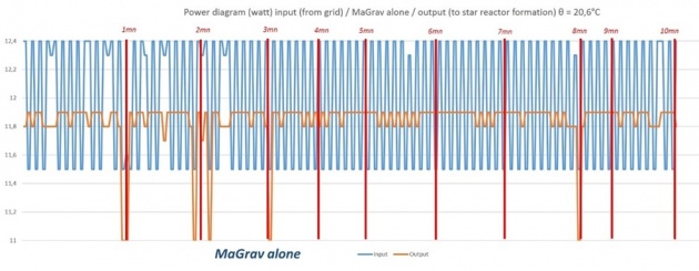
After three weeks of operation, the MaGrav unit began to indicate power variations on the controllers (power consumption output is greater than power consumption input). At the very beginning these variations did not have a significant frequency, in the order of once or twice an hour. As time goes by, these frequencies increase very significantly: three weeks ago, I reported this phenomenon to the Plasma Reactor Group.
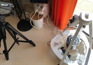
Following these events, I placed a camera that continuously films the controllers (Fig. 7).
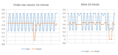
As I had no laboratory equipment, I transferred the films to my video editing station (Fig. 8) and counted the frequency of the pulses minute by minute, as well as their amplitudes. A fortnight ago I presented graphs made with a spreadsheet: they show very well these pulses which number varied at that time from 8 to 13 pulses per minute (Fig. 9).
In recent days, the power read on the sector side controller has dropped to zero for a few seconds and then returned to a "normal" value, while the MaGrav output side controller displays the power consumed by the star formation, and the pulse frequency increases.
On the other hand, my partner and I do tests by mentally asking closed questions to our MaGrav, in such a way that it answers us when using a pendulum: the pendulum oscillates in one direction to answer and the MaGrav is asked to answer by changing the value of absorbed power or (and) that of output power. It seems to be working… I would add that these tests were carried out in different configurations (MaGrav only, MaGrav integrated in the star training – Fig. 10), supplemented by tests on the old version of MaGrav. For the latter, we did not detect a pulse.
Future Work
The vision of the participants in the Plasma Reactor Group and more particularly those of Rick, Mario and Armen's valuable advice make it possible to propose a timetable for the tests:
- Evolution n°2 by modifying only the GaNS CuO and CH3 (Fig. 11),
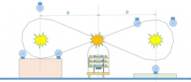
- Configuration of measurements between two inverted stars (Fig. 12),
- Declination with the first disc version using the results of the study [5] proposed in the Plasma Times journal of February 2019.
References
[1] Keshe, M.T. 245th Knowledge Seekers Workshop October 11 2018. Retrieved from YouTube: https://www.youtube.com/watch?v=_ipIO96-5UY
[2] Keshe, M.T. 263rd Knowledge Seekers Workshop February 14 2019. Retrieved from YouTube: https://www.youtube.com/watch?v=eSGu8NrDT78&t=2956s
[3] Keshe, M.T. 270th Knowledge Seekers Workshop April 4 2019. Retrieved from YouTube: https://www.youtube.com/watch?v=s8htkvMQKR4
[4] Keshe, M.T. 276th Knowledge Seekers Workshop May 16 2019. Retrieved from YouTube: https://www.youtube.com/watch?v=zwu9FAv6O4Y
[5] “Visual confirmation of a natural dynamic field flow in GaNSes”. J. Ricard, KF Plasma Times, February, 2019.

